
How does the secondary current of High Accuracy Split Core CT relate to the primary current?
 Oct 30, 2025|
 In the realm of electrical engineering, current transformers (CTs) play a pivotal role in measuring and monitoring electrical currents. Among them, High Accuracy Split Core CTs have gained significant popularity due to their ease of installation and high - precision performance. As a supplier of High Accuracy Split Core CTs, I am often asked about the relationship between the secondary current of these CTs and the primary current. In this blog, I will delve deep into this topic to provide a comprehensive understanding.
Basic Principles of Current Transformers
Before we explore the relationship between the secondary and primary currents of High Accuracy Split Core CTs, it is essential to understand the fundamental principles of current transformers. A current transformer is a type of instrument transformer that is designed to produce an alternating current in its secondary winding proportional to the current flowing in its primary winding.
The basic working principle of a current transformer is based on Faraday's law of electromagnetic induction. When an alternating current flows through the primary winding of the CT, it creates a magnetic field around the core. This magnetic field then induces an electromotive force (EMF) in the secondary winding, which in turn causes a current to flow in the secondary circuit.
The ratio between the primary current ($I_p$) and the secondary current ($I_s$) is determined by the turns ratio ($N$) of the CT. The turns ratio is defined as the ratio of the number of turns in the primary winding ($N_p$) to the number of turns in the secondary winding ($N_s$), i.e., $N=\frac{N_p}{N_s}$. According to the law of conservation of energy and the principles of electromagnetic induction, the relationship between the primary and secondary currents can be expressed as:
$I_p = N\times I_s$
This equation shows that the primary current is directly proportional to the secondary current, with the turns ratio as the proportionality constant.
High Accuracy Split Core CTs: Features and Advantages
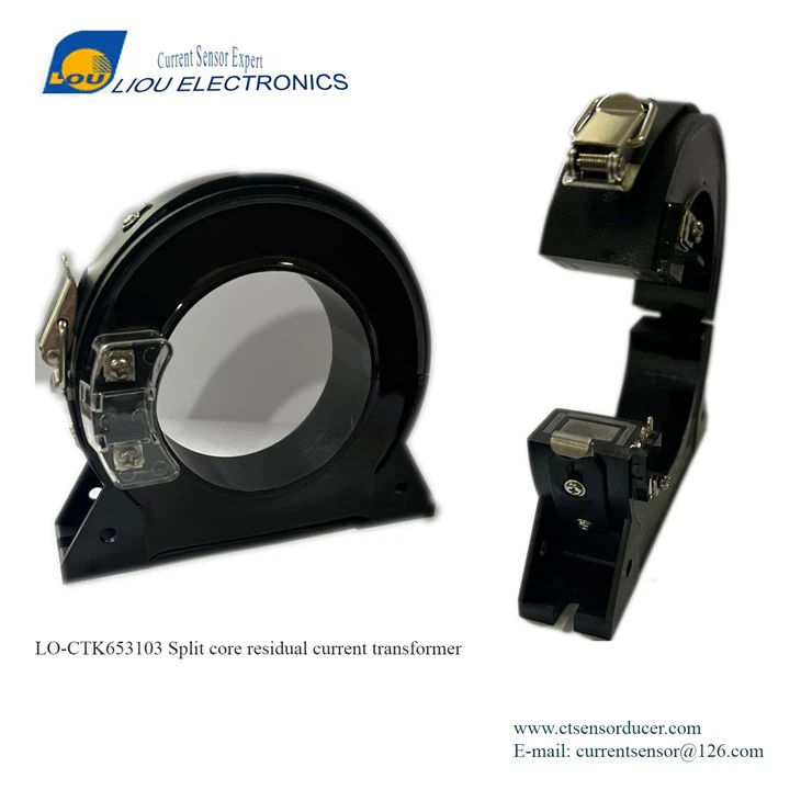
High Accuracy Split Core CTs are a special type of current transformers. The split - core design allows them to be easily installed around existing conductors without the need to disconnect the electrical circuit. This feature makes them highly convenient for retrofit applications and field measurements.
In addition to their easy installation, High Accuracy Split Core CTs are known for their high precision. They are designed to minimize errors caused by factors such as magnetic core losses, leakage inductance, and winding resistance. These CTs typically have a very low ratio error and phase angle error, which ensures accurate measurement of the primary current.
Factors Affecting the Relationship between Secondary and Primary Currents
While the basic relationship $I_p = N\times I_s$ holds true in theory, in practice, several factors can affect the accuracy of this relationship in High Accuracy Split Core CTs.
Core Material and Properties
The core material of a CT has a significant impact on its performance. High - quality core materials, such as silicon steel or amorphous metal, are commonly used in High Accuracy Split Core CTs. These materials have low magnetic losses and high magnetic permeability, which helps to reduce the ratio error and phase angle error. However, factors such as core saturation can still occur if the primary current exceeds the rated value of the CT. When the core saturates, the magnetic flux density in the core no longer increases linearly with the primary current, which can lead to a significant deviation from the ideal relationship $I_p = N\times I_s$.
Load Burden
The load burden connected to the secondary winding of the CT also affects the relationship between the secondary and primary currents. The load burden is the impedance of the external circuit connected to the secondary winding, which includes the measuring instrument and the connecting wires. A high load burden can cause a voltage drop across the secondary winding, which in turn affects the secondary current. To ensure accurate measurement, the load burden should be within the rated value specified by the CT manufacturer.
Temperature
Temperature can also have an impact on the performance of High Accuracy Split Core CTs. Changes in temperature can affect the electrical properties of the core material and the windings, such as the resistance and the magnetic permeability. These changes can lead to variations in the ratio error and phase angle error of the CT. Therefore, it is important to consider the operating temperature range when using High Accuracy Split Core CTs.
Applications of High Accuracy Split Core CTs
High Accuracy Split Core CTs are widely used in various applications where accurate current measurement is required.
Power System Monitoring
In power systems, High Accuracy Split Core CTs are used to monitor the current flowing through transmission lines, distribution transformers, and other electrical equipment. By accurately measuring the current, power system operators can detect faults, monitor the load, and ensure the safe and efficient operation of the power grid. For more information on CTs used in power system monitoring, you can visit Grid - tie inverter analytics & net - metering station monitoring Split Core Current Transformer.
Energy Management
High Accuracy Split Core CTs are also used in energy management systems to measure the energy consumption of different electrical loads. By accurately measuring the current, these systems can provide detailed information about the energy usage of various equipment, which helps in energy conservation and cost reduction.
Industrial Automation
In industrial automation, High Accuracy Split Core CTs are used to monitor the current of motors, drives, and other electrical equipment. This information can be used for fault diagnosis, process control, and predictive maintenance.

Ensuring Accurate Measurement
To ensure accurate measurement of the primary current using High Accuracy Split Core CTs, several measures can be taken.
Proper Installation
Proper installation is crucial for the accurate performance of High Accuracy Split Core CTs. The CT should be installed around the conductor in a way that ensures good magnetic coupling. The split - core should be properly closed to minimize the air gap, which can cause magnetic leakage and affect the accuracy of the measurement.
Selection of Suitable CT
When selecting a High Accuracy Split Core CT, it is important to choose a CT with a suitable turns ratio and rated current. The turns ratio should be selected based on the expected primary current and the range of the measuring instrument. The rated current of the CT should be higher than the expected maximum primary current to avoid core saturation. You can find a wide range of High Accuracy Split Core Current Transformers on our website.
Regular Calibration
Regular calibration is also necessary to ensure the long - term accuracy of High Accuracy Split Core CTs. Calibration should be performed by a qualified laboratory using standard calibration equipment. During calibration, the ratio error and phase angle error of the CT are measured and adjusted if necessary.
Conclusion
In conclusion, the secondary current of High Accuracy Split Core CTs is directly proportional to the primary current, with the turns ratio as the proportionality constant. However, in practice, several factors such as core material, load burden, and temperature can affect the accuracy of this relationship. By understanding these factors and taking appropriate measures, we can ensure accurate measurement of the primary current using High Accuracy Split Core CTs.
If you are in need of high - quality High Accuracy Split Core CTs for your application, we are here to provide you with the best solutions. Our products, such as the High Precision Split Core Residual Current Transformer RCT, are designed to meet the highest standards of accuracy and reliability. Please feel free to contact us for more information and to discuss your specific requirements. We look forward to the opportunity to work with you on your current measurement needs.
References
- Grover, F. W. (1946). Inductance Calculations: Working Formulas and Tables. Dover Publications.
- IEEE Standard C57.13 - 2016, IEEE Standard Requirements for Instrument Transformers.
- Sarma, M. S. (2002). Electromagnetics for Engineers. West Publishing Company.